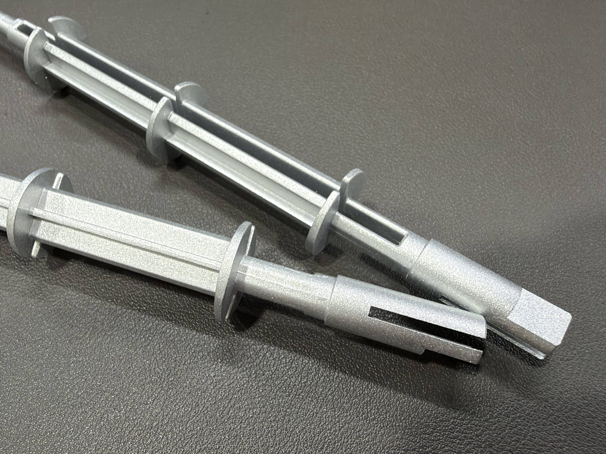
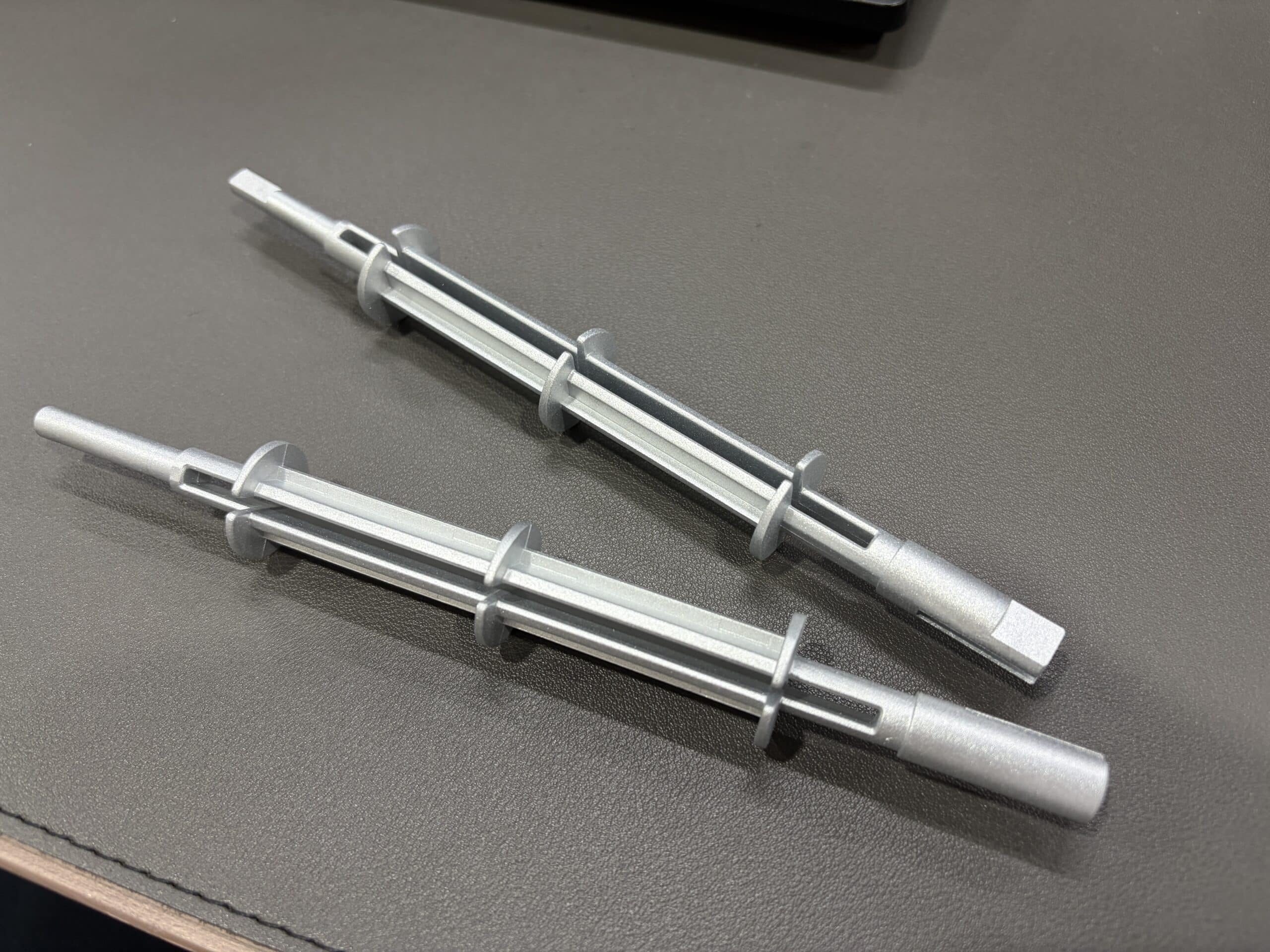
Key Engineering Highlights
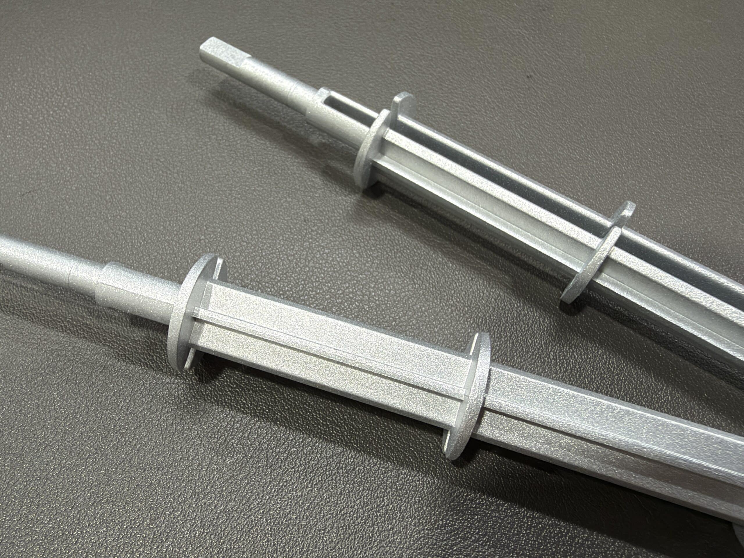
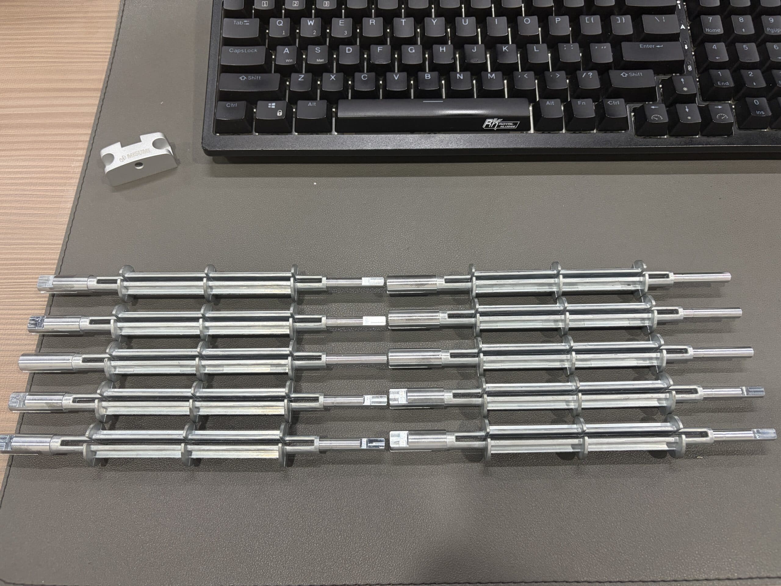
- Ultra-Tight Bearing Journal Tolerance: Precision CNC turn-milled datum journal holding Ø6 h7 (+0/-0.012 mm) and a 5 ±0.025 mm anti-rotation D-flat.
- Full-Length Concentricity & Straightness: Strictly controlled ≤0.04 mm (↗ 0.04 A) circular runout across the entire 185.5 mm slender transmission spindle.
- General Machining & Casting Standard: Produced to ISO 2768-fH (Fine tolerances for machined features, Heavy/Class H tolerances for geometric runout & perpendicularity).
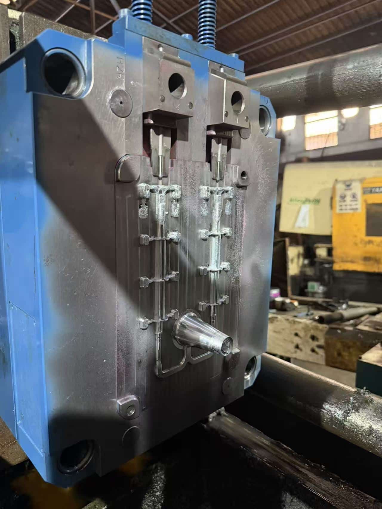
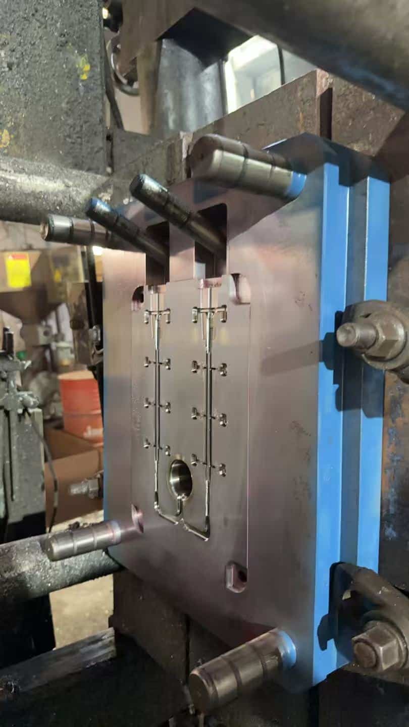
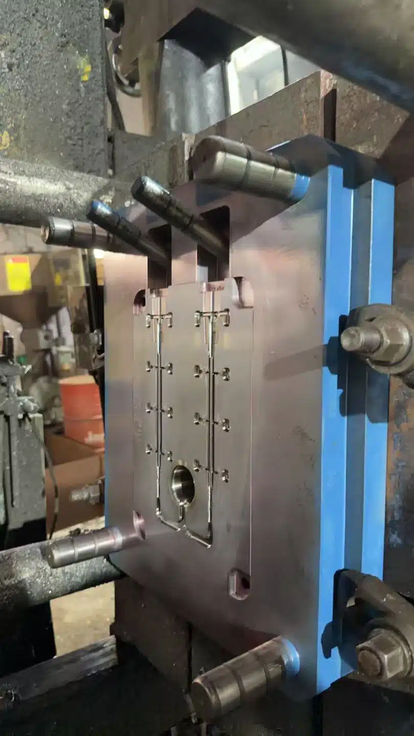
- In-House 1×2 Cavity H13 Tooling: Engineered with top hydraulic/angle-pin core-pulling sliders and 16 lateral overflow wells to prevent cold shuts and porosity in thin Ø21×1.5 mm flanges.
- 50%+ Total Cost Savings vs. Solid Bar Stock: Near-net-shape hot-chamber zinc die casting eliminates heavy rough turning of the cross-ribbed body, restricting CNC operations to critical functional ends.
Product & In-House Mold Gallery




Real Blueprint & Production Technical Specifications
| Parameter / Feature | Verified Production Specification |
|---|---|
| Alloy Material | Zamak 5 (ZnAl4Cu1 / EN 1774 / ASTM AG41A) — High tensile strength & superior castability |
| Single Part Mass | 84.3 g (Verified net finished weight) |
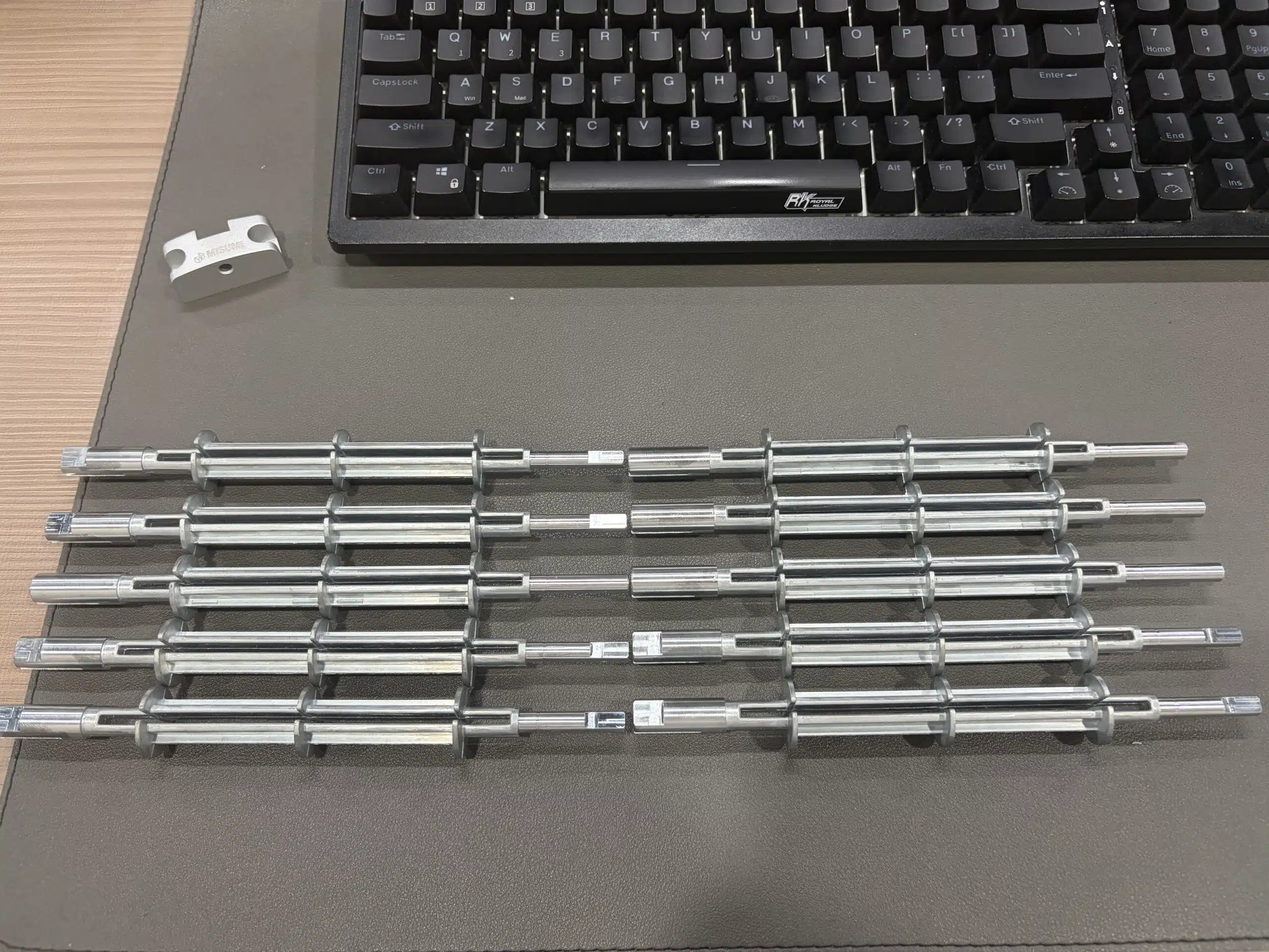
| Overall Length | 185.5 mm slender transmission spindle |
| Cast Body & Flanges | Ø13 h10 cruciform cross-ribbed core with three Ø21 × 1.5 mm notched positioning flanges (near-net cast) |
| Drive End (Journal & D-Flat) | Ø6 h7 (+0/-0.012 mm) precision datum journal with 5 ±0.025 mm CNC-milled anti-rotation D-flat |
| Coupling End (Slotted Sleeve) | Ø10 mm stepped sleeve, 8.5 ±0.03 mm cross-slot width, and Ø5 (+0.05/+0.02 mm) precision axial bore |
| Geometric Concentricity | ≤0.04 mm (↗ 0.04 A) full-length circular runout referenced to Datum A |
| General Tolerance Standard | ISO 2768-fH (Fine linear/angular class & Class H geometric runout/perpendicularity) |
| Die Casting Process & Tooling | Hot-chamber zinc HPDC using in-house 2-cavity hardened H13 steel mold with top core sliders & 16 overflow wells |
| Surface Finish | Fine micro-bead sandblasting on cast body (Ra 1.6–3.2 µm) with bright CNC-turned functional journals |
| Dimensional Inspection | Zeiss / Hexagon 3D CMM full-layout FAI, optical runout gauge, and calibrated Go/No-Go ring & plug gauges |
| Supply Model & Lead Time | T1 mold samples in 20–25 days; full customer mold ownership; pilot runs (100–300 pcs) to high-volume production |
Engineering Breakdown: Hybrid Die Casting + Turn-Mill Workflow
1. 2-Cavity Hot-Chamber Mold with 16 Lateral Overflow Wells & Top Core Sliders
Casting a 185.5 mm slender shaft with three thin Ø21 × 1.5 mm radial flanges requires rapid, turbulence-free metal fill before solidification. Xiamen Mindwell designs and builds the 1×2 cavity H13 mold in-house with balanced fan gates from a central conical sprue, 16 strategically placed lateral overflow wells to evacuate air and cold fronts away from the thin flanges, and precision angle-pin top core sliders to form the axial sleeve cavity cleanly.
2. Single-Setup CNC Turn-Mill Compound Machining
As-cast draft angles and parting-line witness cannot directly satisfy Ø6 h7 (+0/-0.012 mm) bearing fits or Ø5 (+0.05/+0.02 mm) bore concentricity. We transfer raw castings into Swiss-type / turn-mill CNC centers equipped with collet chucks referenced to the precision body datum. In a single clamping setup, the machine turns the Ø6 h7 journal, mills the 5 ±0.025 mm D-flat, bores the Ø5 mm hole, and mills the 8.5 ±0.03 mm coupling slot — guaranteeing ≤0.04 mm circular runout end-to-end.
3. Micro-Bead Blasting & Customizable Surface Sequencing
Following trimming and deburring, parts undergo controlled micro-bead sandblasting for a uniform matte aesthetic and clean edge blending. Critical Ø6 h7 and Ø5 mm functional surfaces are either masked prior to blasting or finish-machined post-blasting according to your blueprint sequence. Optional trivalent chromate passivation, electroless nickel, or zinc-nickel plating can be added for corrosion resistance.
Frequently Asked Questions (B2B Engineering & Sourcing)
Q1: Why choose Zamak 5 die casting + CNC turn-milling instead of machining the entire shaft from steel or brass bar stock?
Machining a Ø21 mm bar down to a Ø13 mm cruciform-ribbed core with three 1.5 mm flanges wastes over 70% of raw material as chips and requires long 4-axis milling cycles. Hot-chamber Zamak 5 die casting forms the entire ribbed body and flanges in ~15 seconds per 2-cavity shot, reducing total piece cost by 50%+ at production volumes while reserving CNC time strictly for the Ø6 h7 and slotted coupling features.
Q2: How do you guarantee ≤0.04 mm circular runout across a 185.5 mm long zinc casting?
We control distortion at three stages: (1) symmetric dual-cavity thermal balance and multi-point ejection in the H13 die to prevent ejection bow, (2) 100% mechanical straightening/runout verification prior to CNC clamping, and (3) single-setup CNC turn-mill finishing using synchronized chuck-to-sub-spindle or live-center support.
Q3: Who owns the 2-cavity H13 die-casting mold?
You retain 100% legal ownership of the custom mold tooling. Mindwell stores, maintains, and refurbishes your H13 mold free of charge in our climate-controlled toolroom for the duration of our manufacturing partnership.
Q4: What CAD files and tolerances do you need to quote a custom drive shaft?
Please send 3D STEP (.stp/.step) or IGES files together with a 2D PDF blueprint marking critical datums (Datum A), GD&T callouts (runout, concentricity, h7/H7 fits), and annual volume. Our engineering team returns a free DFM analysis and factory quote within 24 hours.
👉 Upload Your STEP/PDF Drawing for a Free DFM Review & 24-Hour Quote