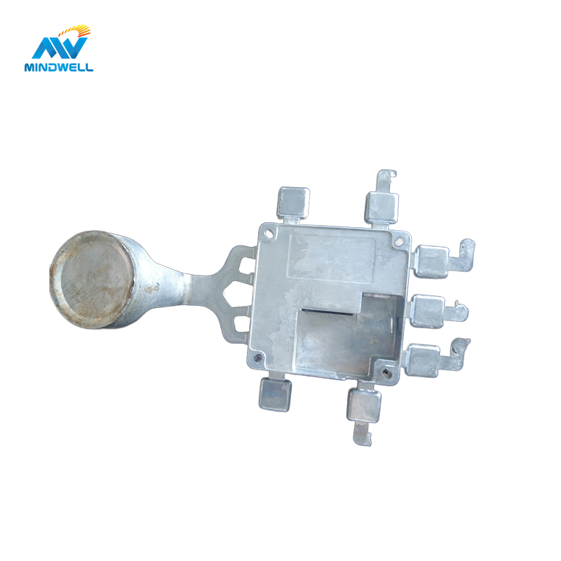
1. Left throttle shaft hole 2. Right throttle shaft hole 3. Gear box spring limit pillar 4. Motor hole 5. Air inlet annulus

To reduce the scrap rate of throttle body ダイカスト製品, a comprehensive analysis of the product structure, mold design, and production issues was conducted. The B15B valve body, consisting of various components such as the left and right throttle shaft holes, gear box spring limit pillar, motor hole, and air inlet annulus, presented challenges during production, leading to a high scrap rate.
B15B Product Parts Structure:
The B15B throttle body parts have dimensions of 107 mm × 103 mm × 63 mm, with varying wall thicknesses and a mass of approximately 400g. The product includes small spring-limited pillars on the gear box side, with specific dimensions requiring careful attention.
Mold Design Plan:
The mold design involves a single mold with three slide blocks, all core-pulled by oil cylinders. A 4000kN die-casting machine and a φ60mm punch are utilized. The runner system is designed for optimal alloy flow into the cavity.

Problems in the Production Process:
Casting Undercast:
- Under-casting of the gear box limit column was addressed by adjusting injection stroke and rapid pressing speed, but these changes were ineffective.
- A solution involved adding an exhaust pin to the deep cavity part of the mold, specifically the small column part, to allow gas discharge during alloy liquid entry.
Under-casting around the Gearbox:
- Mold flow analysis identified undercasting at the end of the feed, lacking an overflow system.
- The solution included adding a mold near this part to facilitate the removal of cold material and gas from the mold cavity.
Pores After Processing:
- Excessive air holes at the bottom of the inner gate and in the air inlet annulus were identified as post-processing defects.
- For annular air holes, the solution involved enhancing the cooling of the core to reduce pore formation near the docking position of the two cores.
- For pores at the bottom of the inner gate, adjusting the inner gate slope from 27° to 35°, as per die-casting mold design manual recommendations, effectively addressed the issue.
Conclusion:
Systematic analysis and targeted improvements, such as adding exhaust pins, modifying the mold structure, and adjusting inner gate slopes, successfully reduced the initial waste rate of 48.52% to less than 10%, leading to substantial economic benefits in the production process.