Abstract: Aiming at the phenomenon that aluminum alloy castings are often accompanied by defects such as air holes, shrinkage cavities, and cold shuts during the die-casting filling process, taking the aluminum alloy gearbox casing of an automobile as an example, the structural characteristics of the gearbox casing are analyzed, and the pouring system and cooling system are analyzed. , The core-pulling structure is designed, the optimal process parameters are determined, after testing and analysis, and finally verified by the actual die-casting production, the rationality of the process plan is confirmed. The results show that: when the fixed mold temperature is 200 ℃, the movable mold is 220 ℃, the pouring temperature of aluminum liquid is 670 ℃, the slow injection speed is 0.18 m/s, the fast injection speed is 4.5 m/s, the pressure of the inner runner is When the injection speed is 48 m/s and the mold retention time is 30 s, the forming quality of the casting is better. Reasonable die-casting process design can not only improve production efficiency and product qualification rate, but also simplify the mold design and manufacturing process and reduce mold development costs.
Aluminum alloy has the advantages of low density, high strength, corrosion resistance, wear resistance, good thermal conductivity, easy processing, and beautiful appearance. It is widely used in automobiles, aviation, machinery, communications and other fields. The forming methods of aluminum alloy mainly include pressure casting, sand casting, squeeze casting and so on. At present, 49% of aluminum alloy products are formed by die casting. Die-casting aluminum alloys are widely used, accounting for more than 75% of the total output of die-casting parts. Die-casting has many advantages such as good product quality, high dimensional accuracy, and suitable for mass production. In the production process, due to the physical changes of aluminum alloy castings accompanied by thermal expansion and contraction, defects such as pores, shrinkage cavities, cold shuts, and cracks will inevitably occur, which greatly affects the production qualification rate of aluminum alloy castings. With the increasingly stringent requirements for aluminum alloy casting products in the automotive field, the foundry industry needs to continuously optimize the die-casting process to meet the needs of product performance.
1.Product structure analysis
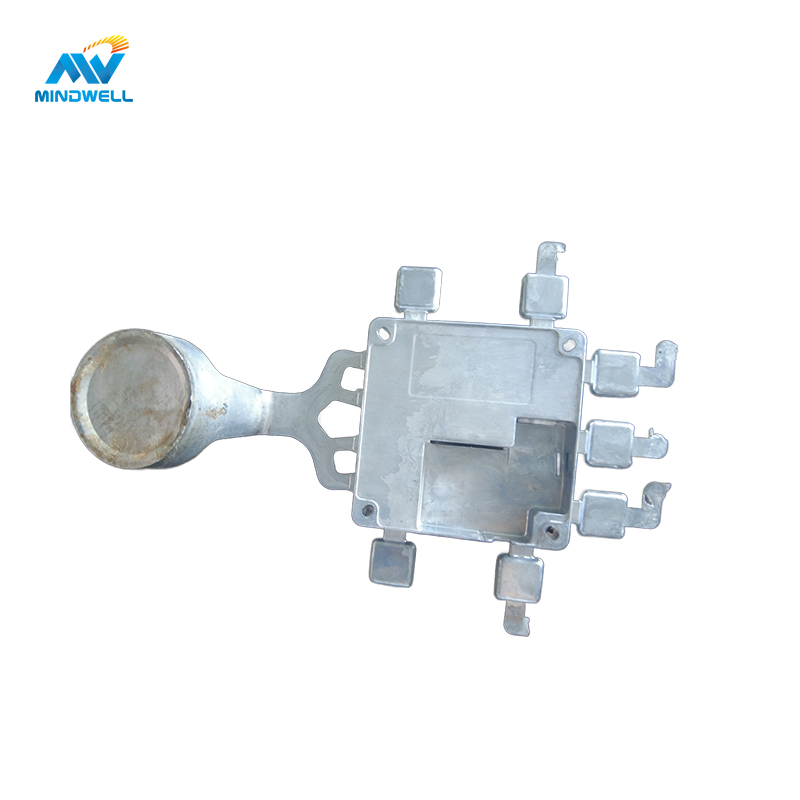
A newly developed automotive aluminum alloy gearbox shell is shown in Figure 1. The product structure is very complex, with concave and convex structures such as oil pipes, reinforcing ribs, and mounting holes all over the surface, so the mold has a side core-pulling mechanism. The wall thickness analysis of the gearbox casing is shown in Figure 2. The material of the product is AlSi9Cu3, the shrinkage rate is 0.6%; the maximum external dimension is 456 mm×381 mm×275 mm; the weight is 9.9 kg; the average wall thickness is 4 mm; there are many oil passage holes, so the density requirement is high, and the porosity requirement is High, strict leak detection requirements, sample submission requirements are porosity not higher than 5%, pores not larger than 3 mm.

Figure 1

Figure 2
2.Mold design
2.1 Establishment of the parting surface
In the die-casting mold, the selection of the parting surface generally needs to ensure that the casting remains on the side of the movable mold after the mold is opened, which is convenient for ejection, and is set at the largest section of the die-casting outline. Due to the complex structure of the product, the internal structure cannot be formed directly, and the parts that are inconsistent with the opening direction of the movable and fixed molds need to be formed with the help of sliders. And the product needs to set a certain demoulding slope to facilitate the later mold opening. The parting surfaces of the upper, lower and right sliders and the fixed and movable molds are shown in Figure 3. Figure 3a is the parting line of the lower slider, Figure 3b is the parting line of the right slider, Figure 3c is the parting line of the upper slider, and Figure 3d is the parting line of the movable and fixed mold. Determining the proper parting surface is the key to mold design.

Figure 3
2.2 Gating system design
2.2.1 Inner runner design
The inrunner is the most important element in the die-casting process plan, which directly determines the product quality and production process. It is set in important or poorly flowing product parts to ensure that the flow form inside the cavity is as consistent and stable as possible. See formula (1) for the calculation formula.
An =G/ρvgt (1)
In the formula: An is the cross-sectional area of the ingate, ㎡; G is the mass of the molten metal passing through the ingate, which is taken as 10.9 kg; ρ is the density of the molten metal, which is taken as 2.7×10³ kg/m³; vg is the metal at the ingate The speed of the liquid is 40 m/s in the table; t is the filling time, and it is 0.07 s in the table. Calculated by formula (1), An is 1 441 m㎡.
2.2.2 Runner and overflow system design
The runner is used to connect the sprue and the inner runner, and the cross-sectional area of the runner should be designed to make the sprue to the inner runner smaller and smaller, which helps to ensure a certain The pressure can prevent the eddy current from appearing in the pouring process. The design of the overflow system is an important part to ensure the quality of castings. Its function is to discharge the gas, cold material, inclusions at the front of the molten metal and the liquid at the confluence of the metal to eliminate the defects of the die casting. The structural characteristics of the product determine the arrangement of the runners, and the arrangement of the slag ladle is generally determined according to the results of the mold flow analysis. The function of the exhaust groove has a great influence on the internal pores of the die casting. The ideal state is that the cross-sectional area of the exhaust groove reaches more than 50% of the cross-sectional area of the ingate. The exhaust groove is generally used in conjunction with the overflow groove. The daily maintenance and cleaning of the exhaust groove is necessary to ensure normal production.
2.3 Cooling system design
In the die-casting mold, the design of the cooling system is conducive to controlling the temperature of the mold, so that the internal heat can reach a state of dynamic balance, thereby ensuring the quality of the product. Figure 4 is a cooling water circuit diagram for the fixed and movable molds. Figure 5 is a three-dimensional model of the product pouring system with a cooling system. The cooling system includes water channels and some high-pressure point cooling mechanisms designed for certain specific positions. The high-pressure point cooling is set in the area with a long solidification time to cool down the position alone.

Figure 4

Figure 5
2.4 Core-pulling mechanism design
For the side holes and undercuts that are not consistent with the parting direction and are not easy to be directly formed, the core-pulling structure is generally used. In the die-casting process, for the gearbox casing, the mold opening sequence is after the movable and fixed molds are separated, the core is pulled first, and then ejected. As shown in Figure 6, for the two side holes of the marked box in the figure, because their direction is inconsistent with the mold opening direction, there is a certain mold drawing angle, so these two positions are formed by hydraulic cylinder core pulling structure. According to the structural features of the product, the core-pulling structures of the two hydraulic cylinders are arranged on the movable mold.

Figure 6
3.Selection of die casting machine and process parameters
3.1 Selection of die casting machine
The choice of die casting machine depends on the injection energy, pressure chamber capacity, clamping force and mold installation size, etc. The clamping force is used to overcome the expansion force during die-casting production, so as to lock the parting surface of the mold, so as to prevent the splashing of molten aluminum. Normally, the clamping force of the mold should be greater than the expansion force calculated theoretically. Otherwise, the mold cannot be locked tightly, the pressure in the cavity cannot be guaranteed, and the liquid aluminum is likely to overflow from the parting surface during the filling process, resulting in defects such as flash, which seriously affects the dimensional accuracy of the casting. The expansion force formula can be expressed as follows:
(1) Expansion force when the mold has no eccentricity:
P=pA (2)
(2) When there is a core-pulling mechanism, the normal force on the slope of the wedge block:
P=p1A1 tan α (3)
In formula (2) and formula (3): P is the expansion force on the mold parting surface, N; p is the injection specific pressure MPa; A is the projection of the casting, gating system, and overflow groove on the parting surface sum; P1 is the oblique normal force of the wedge block, kN; A1 is the projected area of the forming part of the lateral movable core, m2; α is the inclination angle of the wedge block.
(3) Calculation of clamping force:
T=KF total (4)
In the formula: K is the safety factor, here take 1.2. Check the recommended injection specific pressure value of aluminum alloy. For airtight parts, the recommended injection specific pressure value is 80-120 MPa, here 90 MPa is taken, and the inclination angle of the slider is 10°. After calculation, the required clamping force should not be lower than 31 161.6 kN. According to the calculation results of the clamping force and the verification of the installation size and the mold opening stroke, a die-casting machine of 3200T or above is used, and the model of the die-casting machine is finally selected: Buhler 3200T. In addition, parameters such as the pressure chamber capacity and installation dimensions of the die-casting machine also meet the requirements.
3.2 Die-casting process parameter selection
The basis of die casting process design is flow, solidification and forming theory. Choose reasonable die-casting process parameters and carry out trial operation of die-casting production. The diameter of the pressure chamber is determined to be 140 mm, and the die-casting process parameters of the optimal mold preheating temperature, pouring temperature, and punch speed are explored. Set mold preheating temperature to 140, 160, 180, 200 and 220 °C, pouring temperature to 650, 670, 680, 690 and 700 °C, injection speed to 0.1, 2.5, 3.5, 4.0 and 4.5 m/s . Carry out multiple orthogonal tests in turn, analyze and compare to get the best process parameters.
3.2.1 Mold preheating temperature
The preheating temperature of the mold has an important impact on the quality of the product. Generally, the preheating temperature of the mold is above 180 ℃, which is about 1/3 of the pouring temperature. For products with thin walls or complex structures, the temperature can be adjusted appropriately. At this time, the quality of the casting better. If the mold preheating temperature is set too low, the casting is prone to cracks due to increased shrinkage stress; if the mold preheating temperature is too high, the preheating time will be increased, prolonging the production cycle and reducing production efficiency. After many times of debugging, the more reasonable mold preheating temperature is controlled at 200 ℃ for the fixed mold and 220 ℃ for the moving mold.
3.2.2 Pouring temperature
The pouring temperature is the average temperature at which the molten metal enters the cavity from the press chamber, expressed by the temperature value on the holding furnace. The pouring temperature has an important influence on the product quality. When the temperature is too high, the shrinkage is large, the gas solubility is large, and the casting is prone to cracks, coarse grains and sticky molds; . In addition, it is related to the injection speed and alloy composition. After many tests, the pouring temperature is better at 670 °C.
3.2.3 Injection speed
The aluminum liquid is filled into the cavity, and the injection speed is divided into two stages: slow injection speed and fast injection speed. The slow injection stage refers to the movement process in which the punch pushes the aluminum liquid forward until the punch pushes the aluminum liquid in the pressure chamber into the inner runner, and the fast injection stage refers to the injection speed of the punch when the aluminum liquid fills the cavity. The fast injection speed is closely related to the filling quality. If the injection speed of the punch is too low, the casting cannot be formed or the quality of the forming is poor. Increase the injection speed, thereby improving the fluidity of the molten aluminum, and avoiding defects such as flow marks and cold shuts. After many times of practice, the best fast injection speed of this product is 4.5 m/s. The relationship between the injection speed of the inner runner and the fast injection speed is:
VnAn = VkAk (5)
In the formula: Vn is the injection speed of the inner runner, m/s; An is the area of the inner runner, and An =1 450 m㎡ is obtained from formula (1); Vk is the fast injection speed, which is selected as 4.5 m/s; Ak is the pore area inside the pressure chamber, and the diameter of the pressure chamber is 140 mm. After calculation, the speed of the inner runner is 48 m/s.
4.Die casting production process
The injection process of this product is divided into five stages:
- ① pouring stage;
- ② low-speed filling stage Ⅰ (slow-speed sealing);
- ③ low-speed filling stage Ⅱ, metal liquid accumulation;
- ④ high-speed switching and filling stage;
- ⑤ pressure boosting compaction stage.
After the injection process is over, the die-casting machine opens the mold, and at the same time, the core-pulling mechanism of the static mold pulls the core-continues to open the mold, and the movable mold core pulls-continues to open the mold and eject the die-casting part-the pick-up manipulator takes out the die-casting part-spraying the manipulator to spray the mold release agent , to complete a die-casting process cycle. Fig. 8 is the final die-casting product of the aluminum alloy gearbox casing. The surface of the gearbox housing has a clear outline, and there are no defects such as fins, cracks, pores, and cold shuts on the surface. After subsequent machining, it passed the verification of the high and low pressure leak test on the test bench.

Fig. 8
Conclusão
- According to the structural characteristics of the aluminum alloy gearbox shell, design the die-casting mold for it. The design mainly includes: the determination of the parting surface, the design of the gating system, the design of the cooling system, and the design of the core-pulling structure. The structure of the die-casting mold has an important influence on the forming quality of the casting.
- After several tests, the optimal process parameters are: the fixed mold temperature is 200 ℃, the moving mold temperature is 220 ℃; the aluminum liquid pouring temperature is 670 ℃; the slow injection speed is 0.18 m/s, and the fast injection speed The casting speed is 4.5 m/s; the injection speed of the inner runner is 48 m/s; when the mold retention time is 30 s, the forming quality of the casting is good, and it meets the technical requirements after inspection and testing.
- In view of the problems such as pores, cold shut, and leakage in aluminum alloy die castings, by optimizing the die casting process, the production cost can be greatly reduced, the production cycle can be shortened, and the economic benefits can be improved.
The above are the main points of mold design and process optimization for die-casting of aluminum alloy gearbox housing, which are also the experience we have continuously summarized from die-casting production. Our company specializes in customized aluminum alloy die-casting services, which are used in trucks, automobiles, motorcycles and other industries. If you have ideas for custom design of gearbox housings, welcome to communicate with us.