The die-casting mold is a pivotal cog in the die-casting production wheel. Its significance is paramount for ensuring the smooth progression of production and the excellence of castings. It forms an interdependent relationship with the die-casting production process and operational aspects, exerting mutual influence and restrictions.
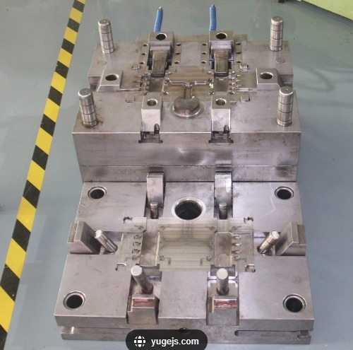
The pivotal functions of the die-casting mold encompass several crucial aspects:
- Defining the shape and size tolerances of castings
- Governing the filling status of molten metal via the gating system
- Control and adjustment of the heat balance during the die-casting process
- The mold’s strength serves as the limit for maximum injection pressure.
- Significantly impacts the overall production efficiency of die-casting processes.
Die casting mold structure
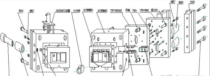
The structure of a die-casting mold typically consists of a fixed mold and a movable mold, intricately linked to the head plate and middle plate of the die-casting machine. The fixed mold is securely attached to the machine’s head plate, while the movable mold is positioned on the middle plate and operates in coordination with the machine’s movement for closure and separation from the fixed mold.
The die-casting mold comprises essential components serving distinct purposes:
- Fixed Mold (often referred to as the front mold)
This primary component of the die-casting mold is vital, linking to the injection part of the die-casting machine. It remains fixed within the machine’s injection section, contributing to the die-casting cavity. It consists mainly of a fixed mold insert, sleeve plate, guide pillar, wedge block, inclined guide pillar, sprue sleeve, and core pulling mechanisms. - Movable Mold (often termed the rear mold)
Another significant segment of the die-casting mold, the movable mold, complements the fixed mold to form a unified structure. Typically affixed to the middle plate of the die-casting machine, it moves in conjunction with the machine, operating the core pulling and ejection mechanisms. - The core-pulling mechanism, also known as the line position, serves to manage the movement of molded parts incongruent with the mold’s opening direction. It encompasses elements like the inclined guide pillar, side core, slider, guide chute, limit block, screws, springs, nuts, and other related parts.
- The oblique pin, or oblique guide pillar, facilitates the extraction of the core during the mold’s opening. Its structure, primarily oblate in shape, aims to prevent strain on the slider during core-pulling. Parameters such as the bevel angle (α), diameter, and length of the oblique pin are crucial and typically set within ranges to accommodate core pulling force and stroke length. Materials like T8A, T10A, with heat treatment reaching HRC 50-55, are commonly employed for this component.
- The guide chute, on the other hand, functions to restrict the slider’s movement trajectory. It’s usually manufactured from materials like T8A, T10A, 40Cr, and subjected to heat treatment, ensuring an optimal hardness within the range of HRC 42-47.
- The slider functions as a connector between the core and the oblique pin, facilitating the core-pulling movement. During on-site operations, it’s critical for the slider and guide chute to work harmoniously. The pulling distance should not exceed 2/3 of the guide chute’s length to prevent molten metal from causing the slider to jam. Parameters such as the slider’s height (B), width (C), and length (A) are tailored according to core size, ensuring stability and functionality. The material used, including T8A, T10A, and 40Cr, undergoes heat treatment to achieve an optimal hardness ranging from HRC 42-47.
- The limit block serves the purpose of securely maintaining the position of the slider once pulled out. This ensures precise reinsertion of the oblique pin into the slider’s oblique hole during mold closure for accurate resetting. It’s typically made from materials like T8A and T10A.
- Screws are employed to affix the limit block onto the movable mold plate.
- Springs, screws, and nuts work in tandem to ensure the slider’s precise positioning after movement. Adequate spring tension, surpassing the slider’s own weight, is crucial for accuracy in slider positioning.
- The wedge block, also known as the inclined wedge, works to withstand counter pressure and prevent the slider from retracting during the injection phase. It’s designed with a specific wedge tightening angle, typically adjusted to the oblique pin angle plus 3° to 5°, secured in place via positioning screw tightening. Commonly crafted from T10A and subjected to heat treatment targeting an HRC range of 42 to 50.
- The hydraulic (cylinder) core pulling mechanism comprises various parts such as the hydraulic cylinder, stroke control switch, connecting rod, side-drawing core, connecting sleeve, fixing plate, support block, and other related components. High-temperature resistant cylinders are a requisite, often procured from designated suppliers.
- The moving mold plate, known as the B plate, functions as a stabilizing support for the fixed mold insert. It endures three types of stresses: tension, bending, and compression, with its size directly impacting the mold’s quality and rigidity. Typically crafted from 45# S50C material.
- The fixed mold base plate, also referred to as the A plate, serves to secure and position the mold within the die-casting machine. It’s designed with two faces: one fastened to the head plate, ensuring mold stability, and the other face combined with the mold body to withstand machine pressure. Precise pressure area and installation hole alignment for the nozzle and pressure chamber of the die-casting machine are crucial. The material commonly used is 45# S50C.
- Cores, inserts, and pins are instrumental in shaping holes or concave positions within the mold, aligning with product specifications. The material typically employed for these components includes H13, DAC, SKD61, DH31S, 8407, 8418, DAC55, and W400, undergoing heat treatment to reach an HRC range of 48–52.
- The fixed mold insert, movable mold insert, and positioning parts constitute die casting size components, with their cavity size contingent upon the casting size plus its corresponding casting shrinkage. Shrinkage rates for various alloys are considered, determining the wall thickness of the insert according to the shape and size of the casting. Material choices include H13, DAC, SKD61, DH31S, 8407, 8418, DAC55, and W400, all treated to achieve an HRC range of 48–52.
- The sprue sleeve ensures efficient injection punch action and smooth metal pressure transmission, forming a sprue to facilitate filling the casting. Its diameter is chosen according to specific casting pressure and weight requirements. A highly glossy inner surface is necessary, particularly for cold chamber die casting machines, impacting the hammer head’s lifespan. Materials typically used for gate sleeves are H13, DAC, SKD61, and 8407. Cooling water jackets commonly utilize 45# material and undergo heat treatment within an HRC range of 46-50.
- The diverter cone serves to regulate the sprue’s cross-sectional area, redirecting molten metal flow and reducing material consumption. Internal cooling systems are integrated into this component. Material choices for diverter cones often include H13, DAC, SKD61, and 8407, with a heat treatment achieving an HRC range of 46-50.
- Guide posts, guide sleeves, and middle supports play crucial roles in ensuring correct mold positioning and guidance during installation and closure. The materials often used for guide posts and guide sleeves are T8A, designed to provide necessary rigidity and wear resistance. Guide pillar diameter calculations follow a formula relating to the mold parting surface area (F) and a coefficient (K: 0.07-0.09). Guide post height ensures safety during mold closure, exceeding the highest core height. These components usually undergo heat treatment within an HRC range of 50-55. Middle supports guide the push plate and fixed plate to the correct positions during ejection.
- Thimbles, or cylinder needles, collaborate with other ejection components to facilitate casting ejection. Their shapes vary, with options like round, square, or specialized shapes, catering to the casting’s specific requirements. Commonly, materials used are H13, SKD61, and SKH51, typically utilizing Datong standard heat-resistant thimbles.
- Ejector panels, bottom plates, and rods fulfill specific functions in guiding ejection components, enduring the forces of ejection rods and ensuring smooth movement along guide pillars. Materials commonly used for these components are 45#. Ejector rods safeguard neck pins and aid in the ejection mechanism’s return when the mold is closed.
- The support block, also known as the mold foot or square iron, anchors one end to the wall plate of the die-casting machine and the other end to the mold body. It bears the machine’s clamping force and the ejection reaction when the casting is released. Reliable fastening is essential, and the size and height must adequately facilitate casting ejection. Often crafted from material known as 45#.
- Pads, also referred to as support blocks or supports, enhance mold rigidity, lessening immediate mold deformation caused by machine vibrations during production. Material commonly used is 45# steel.
- The exhaust plate, or diffusion plate, serves to eliminate air entrapment within the mold cavity during casting formation. Materials typically used for this component include H13, DAC, SKD61, and 8407, often subjected to heat treatment within an HRC range of 42-47.
- Components like lifting eye holes, die punching holes, die opening corners, and code die slots have specific functions, including aiding in lifting the mold, facilitating mold core removal, enabling convenient mold dismantling, and ensuring correct mold installation. Garbage nails prevent impurities from hindering the ejection mechanism’s reset.
- Ejector holes and tie rod screw holes serve the mold ejection and return mechanisms, with specified dimensions and quantities varying based on the machine type. Heating (cooling) oil circuits are designed to balance the mold temperature. Components like mold plates, cores, gate sleeves, and diverter cones are outfitted with oil lines. Oil transport hole sizes and outlet/inlet placements vary depending on the die-casting machine’s tonnage. Oil pipe joints and plugs are equipped with specific thread types and markings, ensuring proper oil flow regulation and management.


