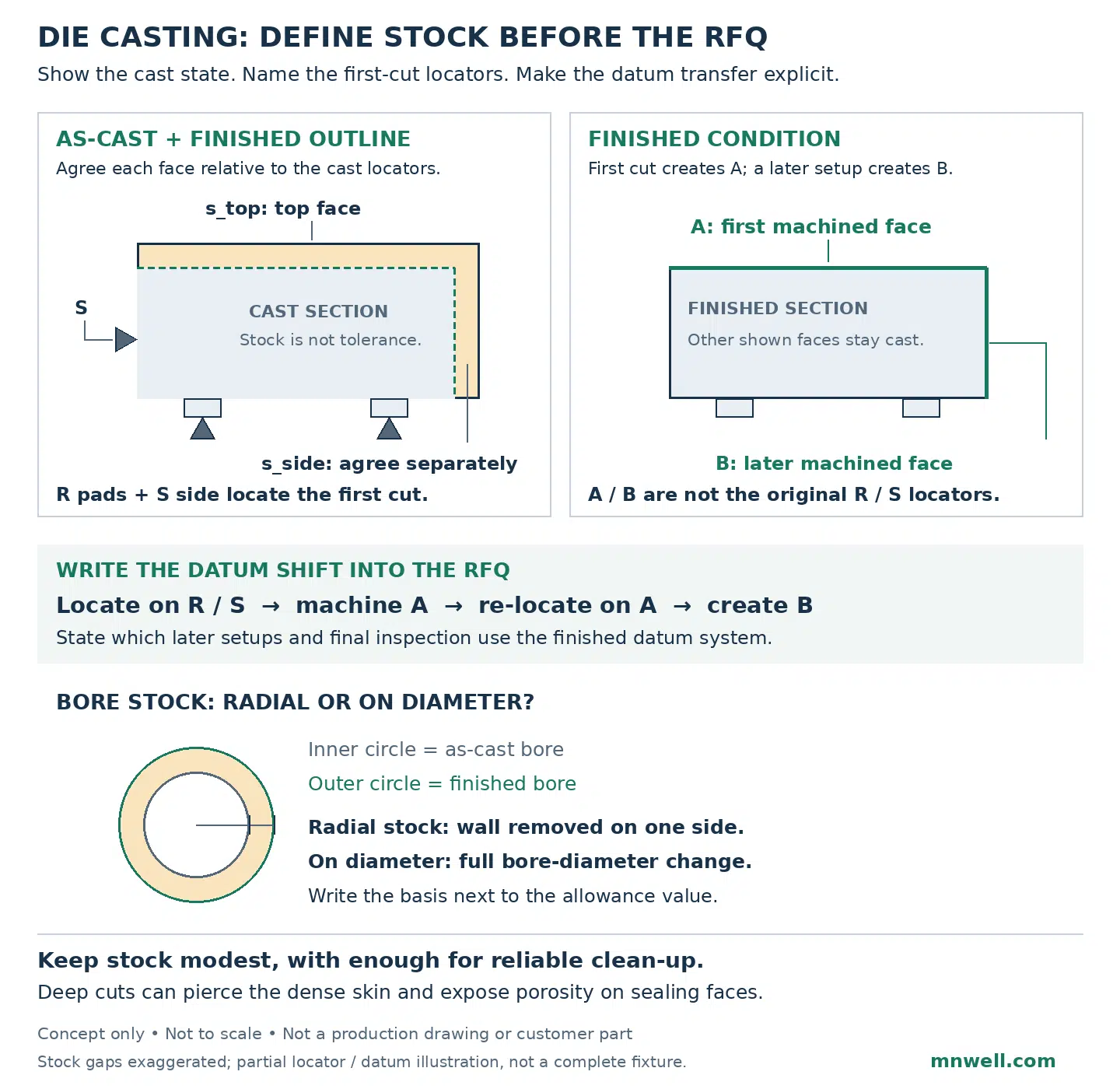
Manufacturing a 185.5 mm slender transmission drive shaft in Zamak 5 (ZnAl4Cu1) presents two competing engineering constraints: thin cross-ribbed flanges that require rapid, turbulence-free molten metal fill, and tight bearing journals requiring Ø6 h7 (+0/-0.012 mm) dimensional accuracy with ≤0.04 mm circular runout across the full spindle length. At Xiamen Mindwell Precision Manufacture, we solved this challenge using an integrated hybrid workflow—combining an in-house 1×2 cavity H13 hot-chamber die casting mold with single-setup CNC turn-mill compound machining.
1. Part Geometry & Blueprint Tolerance Challenges (ISO 2768-fH)
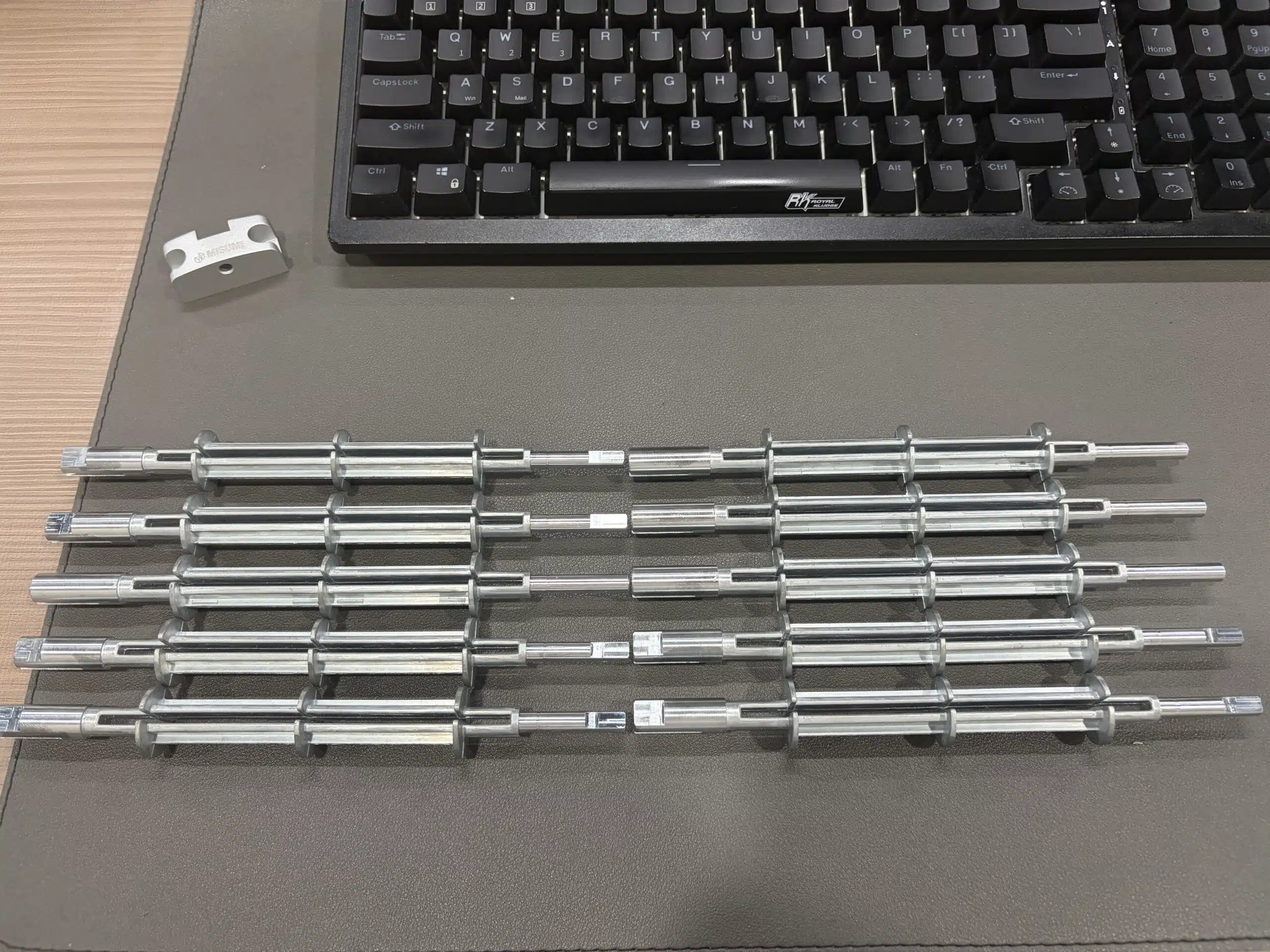
Full-length CNC turning from solid brass or steel bar stock is cost-prohibitive because the central Ø13 h10 body features four deep cruciform stiffening ribs and three Ø21 × 1.5 mm notched positioning baffles. Casting this complex 84.3 g geometry to near-net shape eliminates over 50% of material waste and rough milling time, while restricting precision CNC operations strictly to functional datum surfaces:
- Alloy & Mass: Zamak 5 (ZnAl4Cu1 / EN 1774) | 84.3 g finished weight | 185.5 mm overall length
- General Tolerance Standard: ISO 2768-fH (Fine linear tolerances; Class H geometric runout & perpendicularity)
- Datum A Bearing Journal: Ø6 h7 (+0/-0.012 mm) with a precision milled 5 ±0.025 mm anti-rotation D-flat
- Coupling Sleeve End: Ø10 mm OD with an 8.5 ±0.03 mm milled drive slot and Ø5 (+0.05/+0.02 mm) axial bore
- Full-Length Circular Runout: ≤0.04 mm (↗ 0.04 A) measured across the 185.5 mm spindle

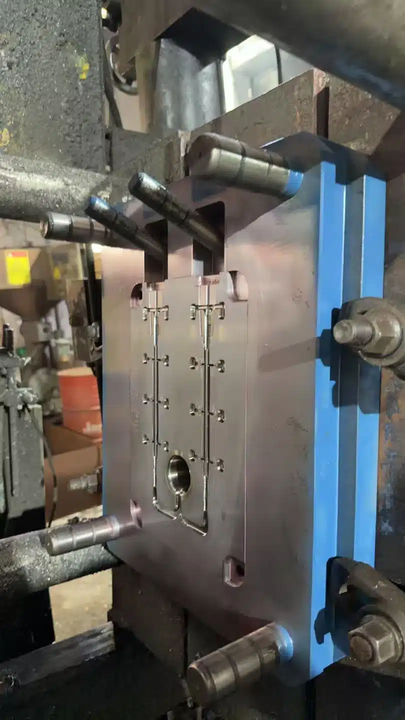
2. Tooling Engineering: 1×2 Cavity H13 Mold with 16 Overflow Wells & Top Core Sliders
Because zinc alloys solidify rapidly in thin sections, filling three 1.5 mm thick Ø21 mm flanges along a 185.5 mm flow path risks cold shuts, gas entrapment, and warpage during ejection. Mindwell’s tooling engineers designed and cut a hardened H13 steel 1×2 cavity mold with:
- 16 Lateral Overflow & Vacuum Relief Wells: Positioned along both parting lines adjacent to the Ø21 mm flanges to flush cooler lead-front metal and trapped air out of the cavity.
- Top Core-Pulling Sliders Driven by Angle Pins: Forms the deep Ø5 mm axial bore on the coupling end cleanly in the casting cycle without secondary deep-hole drilling.
- Balanced Ejection & Thermal Control: Distributed ejector pins along the cruciform rib intersections prevent bending deflection when demolding the 185.5 mm slender shafts.
3. Single-Setup CNC Turn-Mill Compound Machining for Ø6 h7 & ≤0.04 mm Runout
After degating and micro-bead sandblasting to produce a uniform matte finish on the as-cast ribbed body, each Zamak 5 blank is loaded into a precision CNC turn-mill compound center. By turning the Ø6 h7 (+0/-0.012 mm) bearing journal, boring the Ø5 (+0.05/+0.02 mm) end hole, and milling both the 5 ±0.025 mm D-flat and the 8.5 ±0.03 mm coupling slot in a single clamped setup, concentricity errors from multiple re-chucking stages are eliminated.

4. Quality Inspection & Batch Consistency
Every production lot undergoes 3D CMM verification for full-length circular runout (≤0.04 mm relative to Datum A), automated optical/pin gauging on the Ø6 h7 and Ø5 bores, and visual surface audit comparing machined bright surfaces against the micro-bead blasted body. For full technical specifications or to source custom zinc die-cast shafts, explore our Custom Zamak 5 Zinc Alloy Die-Cast Drive Shaft product page.
Have a similar precision die-cast shaft or hybrid CNC machining project? Contact Mindwell Engineering for a Free DFM Review & 24-Hour Factory Quote (STEP / IGES / 2D PDF accepted under NDA).